How does a cvt transmission work? Good question. Let's start with what it is at a high level.
If we want to make a CVT we need to look at what the rules are for this box. A CVT is defined by its lowest and highest gear ratios. In other words the output speed will be in the range of the lowest to highest ratios of the input speed. For example let's say a sample CVT has a lowest ratio of 1:4 and a highest ratio of 1:1. This means that a rotation speed of 100rpm produces an output range of 25 to 100 rpm. The speed of the output varies based on the torque required to drive the output shaft or by a manual control(as in a car with CVT). In this case we want the output speed to be automatically chosen based on the resistance encountered.
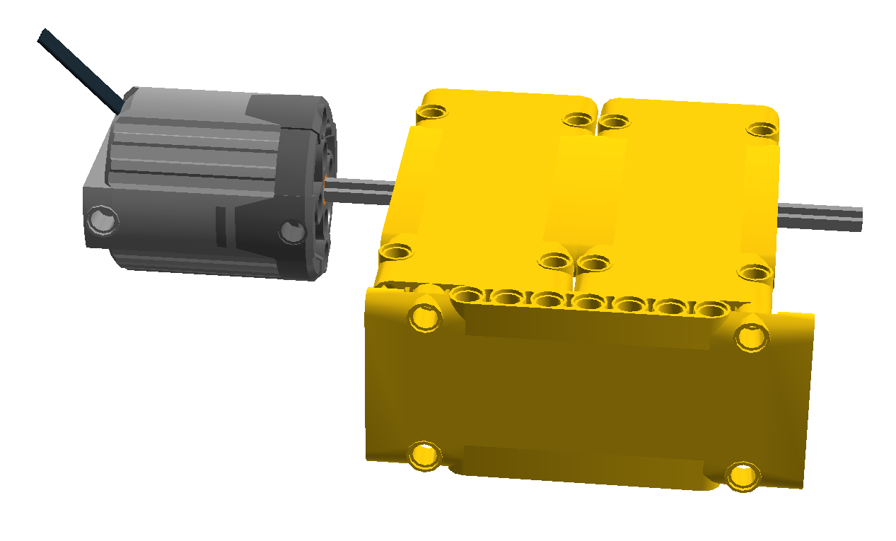
You may have encountered some flavour of this Lego CVT:

The output on the left of the first open differential is a large 24 tooth gear that drives another 24 tooth gear that finally drives the second open differential. Since both gears are the same size it is a 1:1 ratio on that side.
The output on the right of the first open differential is a small 8 tooth gear that drives a much larger 40 tooth gear which in turn drives the second differential. The ratio in this case is 8:40 or 1:5.
Finally the second open differential combines the two drive shafts into one output by averaging the input speeds (or so we hope). It is important that the differentials are of the open type so that power can be instantly transferred back through the drive shafts.
Imagine that there is no friction on the wheel and the gears can all spin freely. In this case we would have both the high and low ratios in the same amount and at the same time. The second differential would combine the two. In the example of 100rpm this would be an addition of 20 and 100 (120) then divided by 2 equaling 60rpm. If the vehicle were moving down a hill it could get up to 100 rpm at its maximum without overpowering the motor. If it were going up a hill then we would expect the lowest speed to be 20rpm. On a small incline this may happen, but there is a problem in practice. What happens when the driven wheel is locked and cannot spin? For the implementation above it is that the net output power is zero. Why is that? Shouldn't it be 20?
This implementation permits all gears to spin in any direction freely so if the output shaft is at zero speed then the power has to go to the other shaft. Since neither shaft entering the second differential have any rotational bias, both shafts fight one another until the one with the least resistance loses and is rotated backwards. Once this happens all power to the ouput shaft is gone except for the amount required to overcome the minimal resistance in the entire system. One solution is to put fly-wheels on the two shafts so that they maintain momentum, but this is not a fix as it still only woks while the output shaft can rotate.
For my purposes this is not sufficient. I can't have the output power become zero if the driven wheel is stalled. In this case I need even more torque with a guaranteed minimum output speed just like a pneumatic drive has a guaranteed amount of output power even at stall.
If we could limit the stall behavior to not permit the counter-rotation then we would have better results. If we use some form of friction wheel or even a limited slip differential there would still be some upper bound that would overcome the internal friction. If we dictated that the gear reduced drive shafts were driven in only one direction we would still have the benefit of the open differentials, but in slightly more limited output.
Looking at the stall case we want power out to equal the lowest ratio side. In other words the output needs to be low gear ratio rotation speed minus no input from the high ratio side. If the lowest gear ratio side wire limited to only rotate in the direction driven then the driven wheel would be guaranteed this lowest rotation speed in the case where it were attempted to be stalled. This does mean that if the motor can overpower a gear or axle in the transmission that something will skip or worse, break. I'm willing to take that chance, but for those not, just add as many clutch gears in parallel as desired on the output of the motor (the Lego BWE uses two on its XL motor).

Here it is again with both gearing sides converted, support structures removed and coloured for easier viewing.
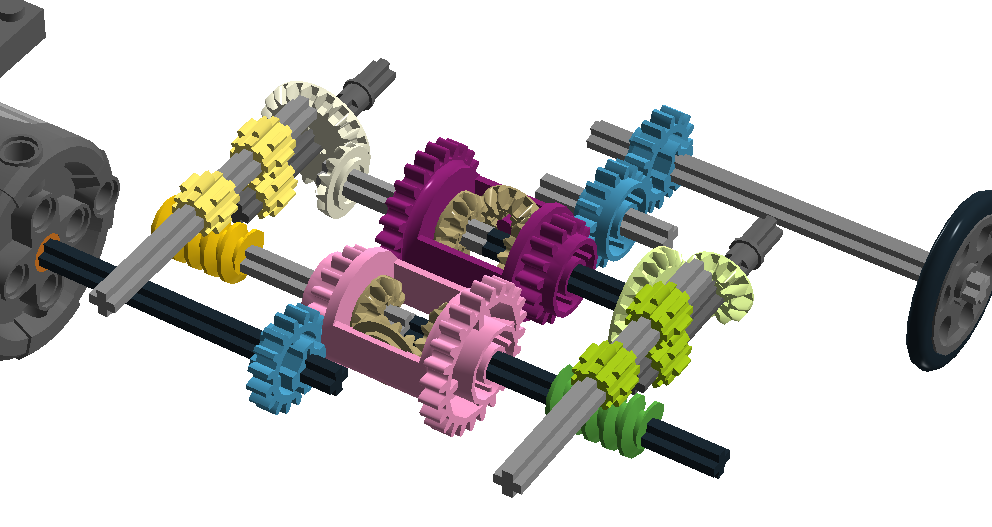
Power from the motor turns the 16 tooth gear that drives the pink differential that drives a grey shaft and a black shaft. The grey shaft drives the yellow gear set for roughly a 1:5 ratio. The black shaft drives the green gear set for a ratio of 1:13. The two gear sets recombine in the purple differential and outputs to the blue 16 tooth gears.The output power equals the motor's output power at all times though the speed varies within the given ratios. In practice the whole system has a problem with using the low gear side even if the motor could drive the high side exclusively because the low side is easier to drive. A simple solution to this is to add a small rotational resistance to the low ratio gearset(green) before it enters the purple differential. The resistance needs to be equal to the gear resistance of running the high side(yellow gears) so that the green side is not used unless it is truly needed because the motor can not drive the high side.
I have built several gear boxes to test this and it does work as desired, but doesn't look like it will fit in an excavator shoe. The next challenge is reshaping it to fit within the dimensions of the MOC's shoe: mostly 5 studs wide, 8 studs tall for the frame not including rollers/sprockets. This means that no gears should protrude from these dimensions at all.
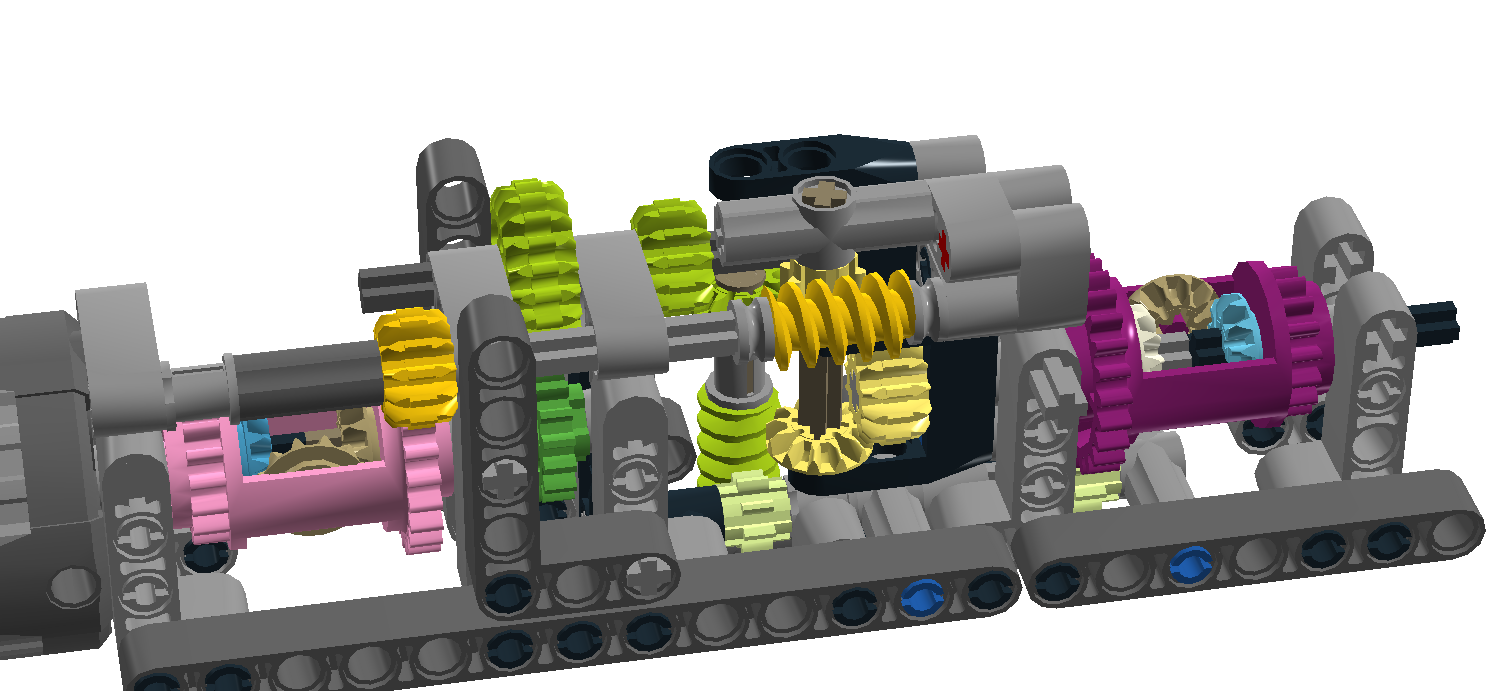
This is getting closer. Now I still have to figure out what I'm going to do about the sprocket.
No comments:
Post a Comment